IN THIS ARTICLE
Material Canvas
Creating material types and shaders in Open 3D Engine (O3DE) is ordinarily a time-consuming process that requires familiarity with the engine, renderer, shaders, data types, file formats, and how everything fits together. It involves manually editing and managing multiple files, writing Amazon Shading Language (AZSL) shader code, editing in JSON, launching the Asset Processor to compile them, addressing any reported errors, then using the O3DE Editor or Material Editor to preview and customize assets.
Material Canvas drastically simplifies, accelerates, and automates the creation of custom shaders and material types by providing a visual scripting editor with familiar tools, workflows, status reporting, and live previews.
Drag-and-drop, connect, and configure nodes to construct material graphs that automatically transform into standard source files for shaders, material types, and materials. The Asset Processor automatically recognizes and processes the generated source files, so other O3DE systems and compoments can use the materials. By default, Material Canvas regenerates and overwrites files whenever you open, edit, and save a graph. The viewport updates to display the results as quickly as changes are made and processed.
Material Canvas is built on top of the same foundations as other O3DE tools like Script Canvas and Material Editor. It is data-driven, customizable, extensible, and scriptable through the settings registry, Python, and C++. All of the current material graph nodes are defined in JSON files that contain snippets of AZSL. You can edit and create new material graph nodes from within Material Canvas.
For more information about features common to Atom tools, menus, dockable panels, and working with documents, see Atom Tools Common Features.
Quick Start
Launching Material Canvas
There are multiple ways to launch Material Canvas.
- From O3DE Editor, select Main Menu > Tools > Material Canvas
- From the Material Component context menu, select Open Material Canvas…
- From the Asset Browser, double-click on a material graph or other file type compatible with Material Canvas.
- From the Asset Browser, right-click on a material graph or other file type compatible with Material Canvas. Then select Open in Material Canvas…
- Material Canvas is also a standalone executable that you can launch directly from a file browser or command console.
- Launch the executable
<build>\bin\profile\MaterialCanvas.exe. Specify the--project-path, followed by the path your project, as a command line argument. For example:
.\<build>\bin\profile\MaterialCanvas.exe --project-path MyProject - Launch the executable
Creating material graphs
You have multiple options to start editing a material graph.
- By default, Material Canvas starts with an untitled, blank material graph document, which you can use to create a new material graph.Note:Until you save the graph, generated files are temporarily output to the
Assets/Materials/Generatedfolder in your project. When you save the graph, the generated files output to the same folder as the graph. - Create a new material graph from a template.
- Select Main Menu > File > New > New Material Graph Document…. This opens the Create Material Graph Document dialog.
- Select a template as the basis for your new material graph.
- Templates are material graphs saved with a special
.materialgraphtemplateextension that designates them as a starting point for new graphs.
- Templates are material graphs saved with a special
- Select a path and file name for the new material graph.
- Open an existing material graph
- Select Main Menu > File > Open > Open Material Graph Document….
- Open or create a material graph from the Asset Browser.
Creating nodes
You can create nodes by dragging them from the node palette to the graph view or using the graph view context menu.
- Drag one of the output nodes, like Base PBR, from the node palette to the graph view. You can start with any nodes but no processing takes place without an output node to drive it.
- Notice that the status bar indicates files are being generated and processed.
- Notice the viewport update to show the generated material on the model.
Configuring nodes
You can change node properties directly on the node in the graph view or in the inspector. If you chose Base PBR or Standard PBR as your output node the material is initially white.
For example, to change the material’s color:
- Change the base color to red (1, 0, 0, 1).
- Notice that the status bar indicates the files are being regenerated and reprocessed.
- Notice that the viewport updates such that the material and model are not red.
Connecting nodes
Connections are a link between one node’s output values to another node’s input values.
The following instruction demonstrates a common scenario for connecting nodes:
- Create a Float4 or Color Input node anywhere on the graph. These are interchangeable but represent the value with different controls in the UI.
- Drag-and-drop the connection wire from that output slot to the base color slot on the output node. When the connection is made, the editable value disappears from the node and is grayed out in the Inspector.
- Notice that the viewport model changes from it’s previous color to the color of the input node. Change the property values of the input node and notice the colors update in the viewport.
For Input nodes, you can also open the generated material or material type in the Material Editor and configure the properties from there as well.
You can create more interesting and advanced graphs by adding and nesting connections between function, texture sampling, time, transformations, and other nodes. Find several examples in the Gems/Atom/Tools/MaterialCanvas/Assets/MaterialCanvas folder.
Navigating Material Canvas
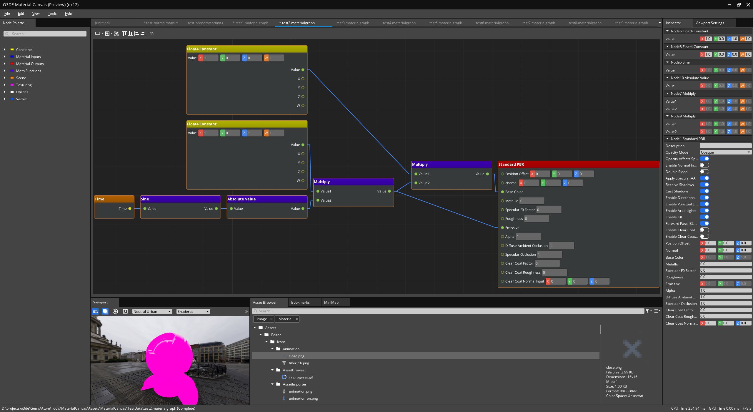
When you launch Material Canvas, you will see the following main window.
For more information about features common to Atom tools, menus, dockable panels, and working with documents, see Atom Tools Common Features.
Document types and views
Material Canvas supports creating, opening, and editing multiple types of documents.
Material Graph documents
Material Graph documents, .materialgraph are the main documents type in Material Canvas. Each open material graph has a corresponding, two dimensional, gridded, graph view, where most editing takes place. All of the data related to nodes, connections, slot values, positioning, selection, and any other metadata about the graph is stored in the material graph document.
Material Graph Node documents
Material Graph Node documents, .materialgraphnode, are JSON files that define each type of node that you can create in Material Canvas. They contain settings for a unique ID, unique name, display name, description, data type, and default values for the node and its slots. Additionally, they declare fragments of AZSL shader code and other metadata that Material Canvas uses to assemble complete shaders. All of the current Material Canvas nodes are specified using material graph node configuration files. Nodes can also be created and registered programmatically using C++ or Python.
Shader Source Data Config Documents
Shader Source Data Config Documents, .shader, are for editing shader configuration files. All of the supporting data types are reflected so you can edit shader source data files in the Inspector or using Python. In the Inspector, all of the options are listed. This is useful to edit shader source data files and creating new templates for material graph output nodes.
Main menu
The main menu contains all of the submenus and actions common to all Atom tools as well as Material Canvas specific actions.
For more information about features common to Atom tools, menus, dockable panels, and working with documents, see Atom Tools Common Features.
Edit menu
In addition to options common to Atom tools, when a material graph document is open and active, there are also options to manage the graph and its elements.
Similar to Script Canvas and Landscape Canvas, you can select, align, delete, duplicate, cut, copy, and paste nodes.
View menu
In addition to options common to Atom tools, there are also options to navigate and manage the graph view, as well as open an editor to configure comment nodes and node group presets.
Tools menu
From the Tools menu, you can toggle dockable windows that are specific to Material Canvas.
Docked windows
Material Canvas provides several additional windows related to working with graphs. Unlike Material Editor, the viewport is also dockable.
Node palette
The node palette contains a tree of all available material graph nodes and other utility nodes, that you can add to a graph. The nodes are organized by category and color-coded by type.
You can do the following actions:
- Hover over each node in the tree to read details about the node.
- Drag nodes from the palette into the active graph view to create an instance of that node at the drop position on the graph.
Bookmarks
Use the bookmarks panel to manage all of the bookmarks on the active graph. You can configure bookmark descriptions and colors bookmarks panel and Inspector.
You can do the following actions:
- Place bookmarks on the graph, like pins on a map, as a point of reference for any important positions.
- Double-click on a bookmark to center the graph view on that position.
Mini Map
The mini map window displays a zoomed-out overview of the nodes and graph. Click-and-drag the mini map to quickly navigate to different parts of the graph.
Viewport
The viewport renders a scene containing a model, with the current material applied to it, under configurable lighting conditions. The viewport window has a toolbar with controls for setting different options related to the grid, shadow catcher, and tone mapping mode. There are also drop downs for selecting the viewport model, lighting preset, and render pipeline. Lighting presets contain all the settings for the skybox, image-based lighting, directional lights, and other settings used in the viewport. Since the introduction of the material pipeline system, render pipelines can also be changed at runtime.
For more information about the viewport and how to interact with it, see Atom Tools Viewport.
Viewport Settings
Use the viewport settings panel to edit the active lighting preset. The changes are reflected in the viewport. Select, create, and save lighting presets from this panel. You can also manage model presets, which are sidecar files for identifying which models are available in the viewport. The viewport settings panel does not currently support undo and redo.
For more information about the viewport settings, see Atom Tools Viewport.
Editing material graphs
Node creation and placement
Nodes are the building blocks of every material graph. Every node serves a purpose, providing data or a distinct piece of functionality that you can add to the graph.
To create and place nodes, do either one of the following:
- Drag nodes from the node palette onto the material graph view.
- Right-click on the graph view and choose a node from the embedded node palette. When you create a node, the node appears at the drop or click position. The node is selected and its properties display in the Inspector for editing.
Depending on system constraints, you can repeat this process add more nodes to a graph. Some operations may take longer to perform based on the number of nodes on a graph or the number of selected nodes.
After you add nodes, move and reorganize them by dragging them to new positions. Access actions in the toolbar and in the Edit menu to change the placement and alignment of the selected nodes.
Node slots and connections
Every Material Canvas node has some number of slots. Slots define properties, inputs, and outputs for a node.
Properties slots have no incoming or outgoing connections. They are often used as constant values or to describe other details about the node.
Input slots have default values that are consumed by and assigned to variables used inside the node. Input slots can only have one incoming connection.
Output slots represent return values from some operation performed by the node. Output slots can have connections to multiple input slots on other nodes. When an output slot is connected to an input slot on another node, the output slot value replaces the input slot value.
Connections are made between input slots and output slots by dragging a connection wire between them. Material Canvas prevents invalid, recursive or cyclic, connections between nodes.
Node types
Material Canvas has different node types that are categorized into logical groups and color-coded based on the function of the node.
Output nodes (main nodes)
The most important node type for a material graph is the main output node. These nodes provide all of the templates and meta data that instruct Material Canvas on what to generate. Material Canvas begins to generate data once an output node, with properly configured template data, is added to a material graph.
At this time, Material Canvas has two output nodes. The Base PBR and Standard PBR nodes contain input slots, options, and templates that you can use to create custom shaders and materials with lighting models and features similar to the core material type counterpart. Not all features have been exposed to the Standard PBR node.
Experiment by dragging one of these nodes onto a material graph. If the automatic graph compilation settings are enabled, which they are by default, several shader files, the material type, and the default material will be generated in the folder containing the material graph file.
Constant nodes
Constant nodes represent constant variables defined in line in shader code. There are several constant nodes corresponding to different data types supported by the AZSL. These nodes should be used to setup any variables that do not need to be exposed to outside of the shader or configurable through materials.
Input nodes
Input nodes represent named variables that will be added to the Material SRG structure with properties and connections exposed in the material type. These properties will be displayed and configurable in the Material Editor and material component. You can also control them through script. Input nodes have additional property slots for you to specify their name, description, and other data to make them easily identifiable. As with constant nodes, there are several different nodes corresponding to data types supported by AZSL and the material system.
Vertex nodes
The vertex node category contains nodes that correspond to different vertex attributes like positions, normals, texture coordinates, and so on. There are nodes for the same attribute in local and world space.
Function nodes
The function node category contains several math related and utility function nodes that process property and input values and return a result. Currently, the majority of the function nodes are wrappers for AZSL intrinsic functions.
Texturing nodes
This category contains nodes related to texture sampling. Note that some texture sampling nodes sample from a constant vector by default. You may require input from a UV node or other varying vertex attribute node to sample using texture coordinates covering a surface or model.
Scene nodes
This category is intended to contain nodes for elements of the Scene SRG. At this time, the only exposed node is Time.
Utility nodes
The utility node category contains standard comment and group nodes used by all of the O3DE, graph editing tools. Comment nodes can be placed throughout the graph to leave notes and descriptions about a particular part of the graph. You can use group nodes as a container for other nodes on the graph. For groups that contain other nodes, you can expand, collapse, and treat them as a single node.
Creating new material graph nodes
Material Canvas nodes, with the exception of utility nodes, are completely defined in JSON configuration files. As mentioned earlier, these files describe the nodes UUID, name, description, category, as well as the layout and details for each slot on the node. Node configurations may have additional settings or meta data to drive the code and data generation process.
The inspector for material graph node documents allows you to create unique node UUIDs, add and remove slots, select data types, configure default values, and manage custom settings for nodes and slots. The inspector also has custom controls for making selections and editing AZSL.
It is possible to create nodes from scratch using tools provided by Material Canvas. However, some of the nodes are simple enough that it might be more convenient to copy an existing material graph node file, update the UUID, and make changes using the tool or directly in JSON.
Material graph node configuration example
Below is a material graph node configuration for a floating-point constant node with one property and one output slot.
{
    "Type": "JsonSerialization",
    "Version": 1,
    "ClassName": "DynamicNodeConfig",
    "ClassData": {
        "id": "{5E2A378E-D27D-43C0-B708-3586FA2293F3}",
        "category": "Constants",
        "title": "Float Constant",
        "titlePaletteName": "ConstantNodeTitlePalette",
        "description": "Create a shader constant with the type and value defined by this node.",
        "slotDataTypeGroups": [
            "inValue|outValue"
        ],
        "propertySlots": [
            {
                "name": "inValue",
                "displayName": "Value",
                "description": "Value",
                "supportedDataTypeRegex": "float",
                "defaultDataType": "float",
                "settings": {
                    "instructions": [
                        "SLOTTYPE SLOTNAME = SLOTVALUE;"
                    ]
                }
            }
        ],
        "outputSlots": [
            {
                "name": "outValue",
                "displayName": "Value",
                "description": "Value",
                "supportedDataTypeRegex": "float",
                "defaultDataType": "float",
                "settings": {
                    "instructions": [
                        "SLOTTYPE SLOTNAME = inValue;"
                    ]
                }
            }
        ]
    }
}
Material graph node configuration attributes
Every node configuration must have a unique ID. This ensures that they are uniquely identifiable, regardless of location on disk, project, name collisions, or other factors.
The node category determines how nodes are grouped together in the node palette tree.
The node title is the name displayed in the node palette and on the top of the node in the graph view. It’s also used to create unique symbol names and variable names in shader code.
The node title palette name is an optional field specifying which style sheet palette to use for the title bar on the node. Style sheets configure styling, coloring, fonts, and other attributes that control how elements in the node palette and graph view are displayed. Style sheets are defined in a separate, application wide file.
The node description is an optional field that’s presented as a tool tip when you hover over a node in the palette.
Slot data type groups contains a delimited list of slots names. The Material Canvas graph traversal and code generation process will enforce that all slot names listed in this field are promoted to the same data type, if they are compatible. Currently, if all of the listed slots reference scalar or vector values than all of the slot values will be promoted to the largest data type. For example, if all of the slots on the node are scalar values but an incoming connection is a three-dimensional vector then all of the other slots will be up converted to three dimensional vectors. This is necessary, in addition to other forms of casting, so that variables generated from different incoming types will be compatible with code and function calls defined in the node.
Material graph node slot configuration attributes
Every slot configuration must have a unique name with respect to the node. The slot name is used to identify and address the slot, set up connections between slots, and create a unique variable name in generated shader code and other files. The name is also used as the display name in the UI, if there is no display name specified. Avoid changing the name because it breaks connections and loses any data associated with the slot.
For display name, specify a more user-friendly name to present in the UI. If no display name is provide, then a name inferred from the slot name.
The description provides more detail about what slots do or represent. This is presented as tool tips when you hover over the node and slot in the graph view.
The supporting data types’ regular expression field is used to acquire which data types are compatible with a slot. With regular expressions , you can query multiple data types that match a specific pattern, or list the data types individually.
The default value field is used to set a specific default value for a slot. This is optional because the system specifies a standard default value when registering all the data types. No explicit default value is assigned in the node configuration then the registered default value will be used.
Material graph node settings
Material graph nodes and slots provide a field for arbitrary settings. Material graph nodes use the settings for data like blocks of AZSL instructions, template file lists, include file lists, and other entries used for material inputs and shader options.
In the previous example, the settings are used to add AZSL instruction blocks and code snippets to create a variable from a property slot and return its value on an output slot.
Material graph node settings for AZSL instructions
Material graph node and slot configurations can both contain settings for AZSL instruction blocks. These instructions settings are simply lines of AZSL code that create variables, assign values, call functions, and anything else that can be done in AZSL.
In the above example, unique instruction sets are added to each input and output slot. The input slots have instructions for creating variables with the slot type and value assigned. The output slot instructions create another variable to hold the result of the multiplication.
During the code generation process, the entire graph is traversed in depth order, and instructions are stitched together from each node to fill in the shader program. For each node, instructions are added in the following order: property slot instructions, input slot instructions, node instructions, output slot instructions. This gives a deterministic flow of data from inputs to outputs. In the final shader code, each variable name is prefixed with a unique identifier for the contributing node.
Use the following macros to insert details about the node or slot in instruction settings.
- SLOTTYPE is substituted with the AZSL data type for the current slot.
- SLOTTYPE(name) is substituted with the AZSL data type for the slot with the specified name.
- SLOTNAME is substituted with the unique, decorated variable name for the current slot.
- SLOTNAME(name) is substituted with the unique, decorated variable name for the slot with the specified name.
- SLOTVALUE is substituted with the value for the current slot unless it has an incoming connection. If there is an incoming connection, it is replaced with the unique variable name for that connection.
- SLOTVALUE(name) is substituted with the value for the slot with the specified name unless it has an incoming connection. If there is an incoming connection, it is replaced with the unique variable name for that connection.
Troubleshooting
Material Canvas viewport does not update immediately after editing graph
Material Canvas automatically launches the Asset Processor if it is not already running. Some graphics related assets must be processed before the main window opens. Wait until Asset Processor is done processing all assets.
The shader compilation process is expensive, complex, and currently managed by the Shader Asset Builder. Material Canvas relies on the Asset Processor and Shader Asset Builder to process, validate, and preview content generated by material graphs. The Asset Processor reports status, error messages, and other notifications as shader and material assets are built. The viewport updates with shader and material previews as quickly as those assets can be processed.
Building shader assets takes more time on Windows than Linux, or other platforms. This is partially because Windows builds shaders for the null renderer, DX12, and Vulkan by default. Registry settings can be configured to disable unused targets and vastly improve shader compilation and preview times. Use the Material Canvas settings dialog to override these settings.
Material Canvas fails to launch
Material Canvas initialize all of the O3DE Gems enabled by your game project to access the same rendering features and assets. To reduce start times and system resource utilization, Material Canvas and the other Atom tools include registry setting files that forcibly disable several standard O3DE Gems that are not needed within the tool.
If Material Canvas fails to launch, then it may be because of dependency issues with Gems in the active project. Check MaterialCanvas.log for any system entity or module initialization errors. If necessary, change or delete the custom registry settings from the Material Canvas project registry folder.