IN THIS ARTICLE
PhysX Ball Joint Component
With the PhysX Ball Joint component, you can create a dynamic ball joint that constrains an entity to the joint with freedom to rotate around the y- and z-axes of the joint.
PhysX Ball Joint component properties
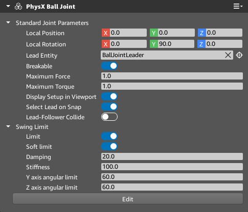
Local Position Specify the position of the joint relative to the entity transform.
Local Rotation Specify the rotation of the joint relative to the entity transform.
Lead Entity Specify the lead (parent) entity that will drive the joint.
Breakable When enabled, the joint will break if sufficient force is applied. Enabling Breakable exposes the Maximum Force and Maximum Torque properties. PhysX Dynamic Rigid Body components that have their Compute Mass property enabled might have very large mass values. If the entity containing the joint component or the leader entity have their Compute Mass property enabled, the Maximum Force and Maximum Torque properties might require very high values to resist breaking.
Maximum Force When Breakable is enabled, specify the maximum force the joint can sustain before breaking. Valid values range from 0.01 to Infinity.
Maximum Torque When Breakable is enabled, specify the maximum torque the joint can sustain before breaking. Valid values range from 0.01 to Infinity.
Display Setup in Viewport When enabled, a cone that represents the orientation and limits of the ball joint and a line that represents the connection between the joint and its follower are displayed. The shape of the cone is defined by the Y axis angular limit and the Z axis angular limit.
Select Lead on Snap When enabled, snapping the joint to an entity in component mode will set the entity as the Lead Entity. The entity containing the joint component is excluded from this operation.
Lead-Follower Collide When enabled, the lead entity and follower entity (the entity containing the joint component) will collide.
Limit When enabled, the lead entity’s movement around the joint axes is constrained by angular limits. Enabling Limit exposes the Soft Limit, the Y axis angular limit, and the Z axis angular limit properties.
Soft Limit When enabled, the lead entity’s movement around the joint axes is allowed to pass the specified limit. With Soft Limit enabled, when the lead entity rotates past the limit, the lead entity’s movement is treated as a spring and will slow, then spring back to the limit area. Enabling Soft Limit exposes the Damping and Stiffness properties.
Damping When Soft Limit is enabled, the spring’s drive relative to the velocity of the follower when outside the rotation limit. Valid values range from 0.001 to 1000000.0.
Stiffness When Soft Limit is enabled, the spring’s drive relative to the position of the follower when outside the rotation limit. Valid values range from 0.001 to 1000000.0.
Y axis angular limit The rotation limit around the joint’s y-axis when Limit is enabled. Valid values range from 0.1 to 180.0.
Z axis angular limit The rotation limit around the joint’s z-axis when Limit is enabled. Valid values range from 0.1 to 180.0.
Edit When clicked, component edit mode is enabled. In component edit mode, all components are locked except for the PhysX Ball Joint component. The properties of the PhysX Ball Joint component can be edited in Perspective. Press Tab to cycle through the component edit modes. Click Done to exit component mode.