IN THIS ARTICLE
PhysX Prismatic Joint Component
With the PhysX Prismatic Joint component, you can create a dynamic prismatic joint that constrains an entity to the joint, keeping the same rotation but allowing it to move freely along one axis.
PhysX Prismatic Joint component properties
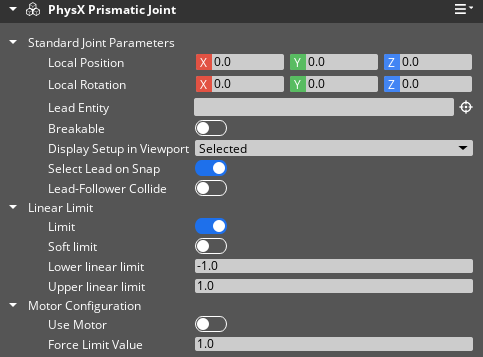
Local Position Specify the position of the joint relative to the entity transform.
Local Rotation Specify the rotation of the joint relative to the entity transform.
Lead Entity Specify the lead (parent) entity that will drive the joint.
Breakable When enabled, the joint will break if sufficient force is applied. Enabling Breakable exposes the Maximum Force and Maximum Torque properties. PhysX Dynamic Rigid Body components that have their Compute Mass property enabled might have very large mass values. If the entity containing the joint component or the leader entity have their Compute Mass property enabled, the Maximum Force and Maximum Torque properties might require very high values to resist breaking.
Maximum Force When Breakable is enabled, specify the maximum force the joint can sustain before breaking. Valid values range from 0.01 to Infinity.
Maximum Torque When Breakable is enabled, specify the maximum torque the joint can sustain before breaking. Valid values range from 0.01 to Infinity.
Display Setup in Viewport When enabled, two planes are displayed showing the limits of the joint. Red and green planes show the Lower linear limit and Upper linear limit. A line displays the connection between the joint and the Follower Entity.
Select Lead on Snap When enabled, snapping the joint to an entity in component mode will set the entity as the Lead Entity. The entity containing the joint component is excluded from this operation. Note: PhysX Prismatic Joint component does not support component mode at the moment.
Lead-Follower Collide When enabled, the lead entity and follower entity (the entity containing the joint component) will collide.
Limit When enabled, the lead entity’s movement around the joint axis is constrained by angular limits. Enabling Limit exposes the Soft Limit, the Positive angular limit, and the Negative angular limit properties.
Soft Limit When enabled, the lead entity’s movement around the joint axis is allowed to pass the specified limit. With Soft Limit enabled, when the lead entity rotates past the limit, the lead entity’s movement is treated as a spring and will slow then spring back to the limit area. Enabling Soft Limit exposes the Damping and Stiffness properties.
Damping When Soft Limit is enabled, the spring’s drive relative to the velocity of the follower when outside the rotation limit. Valid values range from 0.001 to 1000000.0.
Stiffness When Soft Limit is enabled, the spring’s drive relative to the position of the follower when outside the rotation limit. Valid values range from 0.001 to 1000000.0.
Lower linear limit When Limit is enabled, the lower limit of linear motion of the joint. Valid values range from -1000 to 1000.
Upper linear limit When Limit is enabled, the upper limit of linear motion of the joint. Valid values range from -1000 to 1000.
Use Motor When enabled, it uses the motor of the joint.
Force Limit Value When Use Motor is enabled, the force limit value of the joint. Valid values range from -Infinity to Infinity.