IN THIS ARTICLE
Dynamic joints with PhysX
PhysX joint components constrain the position and orientation of one PhysX Dynamic Rigid Body called the follower, relative to another rigid body, called the leader. The follower rigid body will have rotational freedom in zero, one, or two axes around the joint, depending on the type of PhysX joint.
The example image below is a simple demonstration of the different joint types. In each example, the blue sphere is the lead rigid body. The red sphere is the follower rigid body, which must always be a simulated rigid body. The joint component is always part of the follower entity. Once the joint is added to the follower, it needs to be configured to be placed around the leader (using the Local Position and Local Rotation properties of the joint component). In this example, the ball and hinge leaders are static rigid bodies, but they could be kinematic or simulated rigid bodies too.
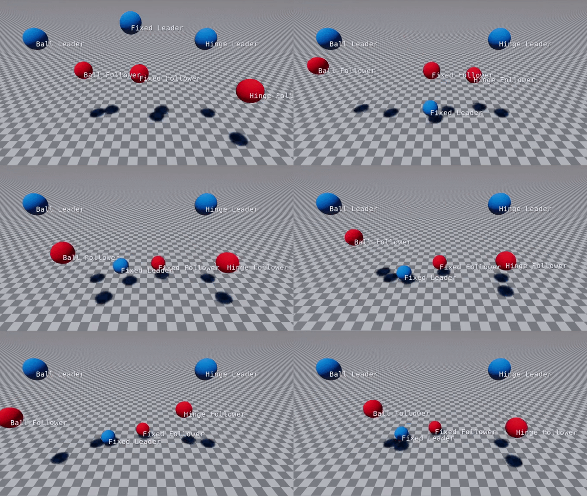
Contents
PhysX joint types
See the linked component reference below for information on the three PhysX joint types:
- PhysX Ball Joint component reference - The PhysX Ball Joint component allows freedom of rotation of the follower rigid body in two axes.
- PhysX Fixed Joint component reference - The PhysX Fixed Joint component does not allow freedom of rotation of the follower rigid body in any axis.
- PhysX Hinge Joint component reference - The PhysX Hinge Joint component allows freedom of rotation of the follower rigid body in one axis.
- PhysX Prismatic Joint component reference - The PhysX Prismatic Joint component keeps the same rotation, but allows the follower rigid body to move freely along one axis.
PhysX joint setup
The setup for each joint type is the same.
Create an entity for the leader rigid body.
Create a new entity. Right click in Perspective and choose Create enity from the context menu.
Add a PhysX Static Rigid Body or a PhysX Dynamic Rigid Body (type kinematic or simulated) component depending if you want the leader to move or not.
Add a PhysX collider to the entity.
Create an entity for the follower rigid body and the joint.
Create a new entity.
Add a PhysX Dynamic Rigid Body (type simulated) component to the entity.
Add a PhysX collider to the entity. This is required for angle limits to work correctly. Joints still work without a PhysX collider but angle limits and might not be enforced. This is also true when using trigger colliders.
Add one of the PhysX joint components:
- PhysX Ball Joint
- PhysX Fixed Joint
- PhysX Hinge Joint
- PhysX Prismatic Joint
Assign the leader entity to the PhysX joint by clicking the Target button to the right of the Lead Entity property and select the leader entity in Perspective.
Adjust the position and orientation of the joint to move it to the leader’s location. Use the Local Position and Local Rotation fields in the PhysX joint component. You can enter component mode by clicking the Edit button and configure the joint in Perspective.
Note:It is not required for a follower rigid body to have an leader rigid body. When a follower doesn’t have a leader it will be constrained on global position.
PhysX Joint configuration using component edit mode
Joint components have an Edit button that enables component edit mode. In component edit mode, you can edit the properties of the joint in Perspective. You can use one of several edit contexts in component edit mode. Press the Tab key to cycle through the edit mode contexts. The current context is displayed at the bottom of the Perspective pane.
Position mode
Applies to: Ball Joint, Fixed Joint and Hinge Joint
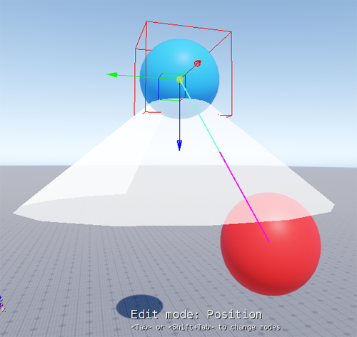
Position mode displays a translate gizmo that you can click and drag to adjust the Local Position of the joint relative to the entity transform.
Rotation mode
Applies to: Ball Joint, Fixed Joint and Hinge Joint
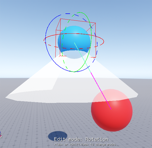
Rotation mode displays a rotation gizmo that you can click and drag on any axis to adjust the Local Rotation of the joint relative to the entity transform.
Snap position mode
Applies to: Ball Joint and Hinge Joint
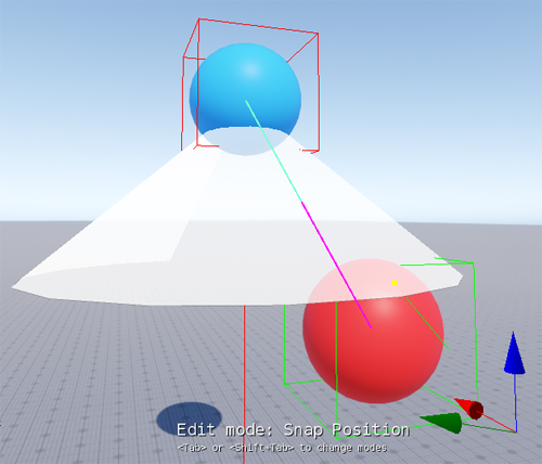
Snap position mode displays a highlight bounding box and target when you hover over an entity. Click the entity to snap the joint Local Position to the highlighted entity’s position. If Select Lead on Snap is enabled in the joint properties, the entity will be assigned to the joint’s Lead Entity property. Any entity can be selected except the follower entity.
Snap rotation mode
Applies to: Ball Joint
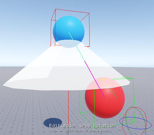
Snap rotation mode displays a highlight bounding box and target when you hover over an entity. Click the entity to snap the joint Local Rotation to the highlighted entity’s rotation. Any entity can be selected except the leader entity.
Maximum Force and Maximum Torque modes
Applies to: Ball Joint, Fixed Joint and Hinge Joint
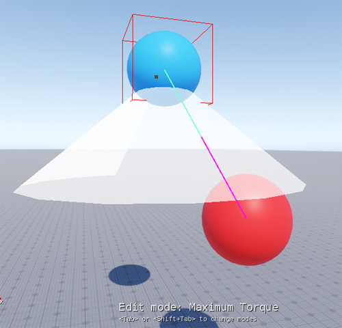
Maximum force and maximum torque modes display a gray box that you can click and drag to adjust the Maximum Force and Maximum Torque properties. The maximum force and maximum torque modes and properties are available only when the Breakable property is enabled for the joint.
Swing limits mode
Applies to: Ball Joint
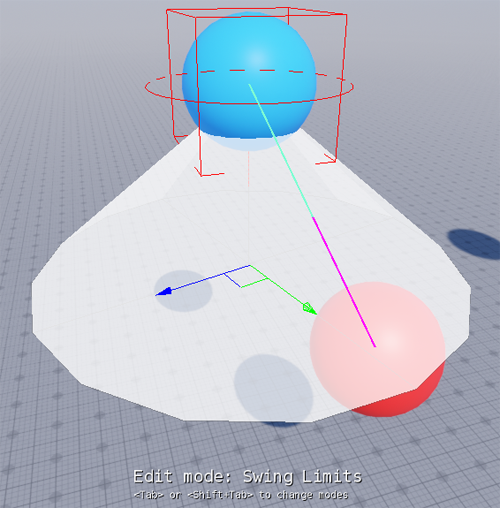
Swing limits mode displays a ring gizmo at the local root of the joint that you can use to rotate the swing limits on the joint’s x-axis, and a scale gizmo that you can use to scale the swing limits uniformly or non-uniformly on the joint’s y- and z-axes. Swing limits mode is available only when the Limits property is enabled for the ball joint component.
Twist limits mode
Applies to: Hinge Joint
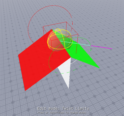
Twist limits mode displays two ring gizmos that you can click and drag to adjust the Positive angular limit and Negative angular limit properties. The red ring adjusts the positive limit and the green ring adjusts the negative limit. Twist limits mode is available only when the Limits property is enabled for the hinge joint component.
Stiffness and Damping modes
Applies to: Ball Joint and Hinge Joint
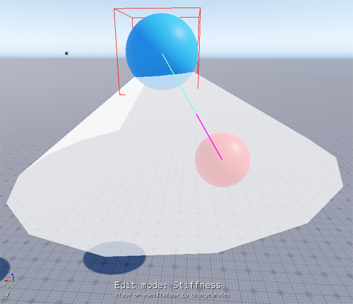
Stiffness and damping modes display a gray box that you can click and drag to adjust the Stiffness and Damping properties. The stiffness and damping modes and properties are available only when the Soft limit property is enabled for the joint.
Notes on stability
The iterative solver used by PhysX joints may not be able to maintain constraints in some configurations. For example, the solver might fail to converge. The result is unstable or unexpected motion during simulation. The PhysX documentation describes configurations that could help avoid such occurrences. Please see Configuring Joints for Best Behavior in NVIDIA’s PhysX Joint documentation.
