IN THIS ARTICLE
Georeference
Overview
Robotics simulations often need to work with geographical locations, in order to simulate behavior and data streams of robots that use global positioning devices and geo-reference APIs. Georeference Component will allow you to work with such data.
How to setup a simulated geographical location
First, add a Georeference Editor Level Component to your level entity.
As a next step, you need to determine which place in your virtual environment will be fixed to a real-world location, by placing an entity in the desired spot. Good candidates for such a place include characteristic locations such as intersections. You need:
- To know the real-world WGS-84 location for this entity.
- To set orientation for the simulation entity as follows (ENU):
- X should point East direction
- Y should point North direction
- Z should point Up
Now, all that is left is to set this entity in configuration of Georeference Editor Level Component alongside WGS-84 coordinates.
Usage
With the Georeference Editor Level Component setup correctly, you can use:
- ROS 2 GNSS Sensor to simulate and publish ROS 2 geolocation data using standard messages.
- Public API to convert geographical location to level coordinate system and vice versa using
GeoreferenceRequestsBus.
Example
Here is a detailed process to build and apply georeference to a simple level that contains a texture. In this particular example, the texture is the orthophoto map of the city center. This texture was imported into O3DE and applied as texture to a plane primitive mesh. The next plane was scaled according to the scale and resolution of the downloaded map.
Next in knowing the location (for example city hall) was placed ENU entity with WGS-84 coordinates:
50.06175556 North
19.93727500 East
Those coordinates need to be added to the Georeference Editor Level Component: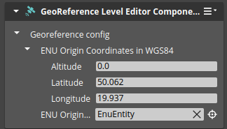
Note:Georeference Editor Level Component can be added only to the level entity.
The used ortophotomap has following geographical directions:
North - up
East - left
The ENU entity needs to be rotated accordingly to follow direction of the underlying ortophoto map.
The correct location of the ENU entity is shown in the image: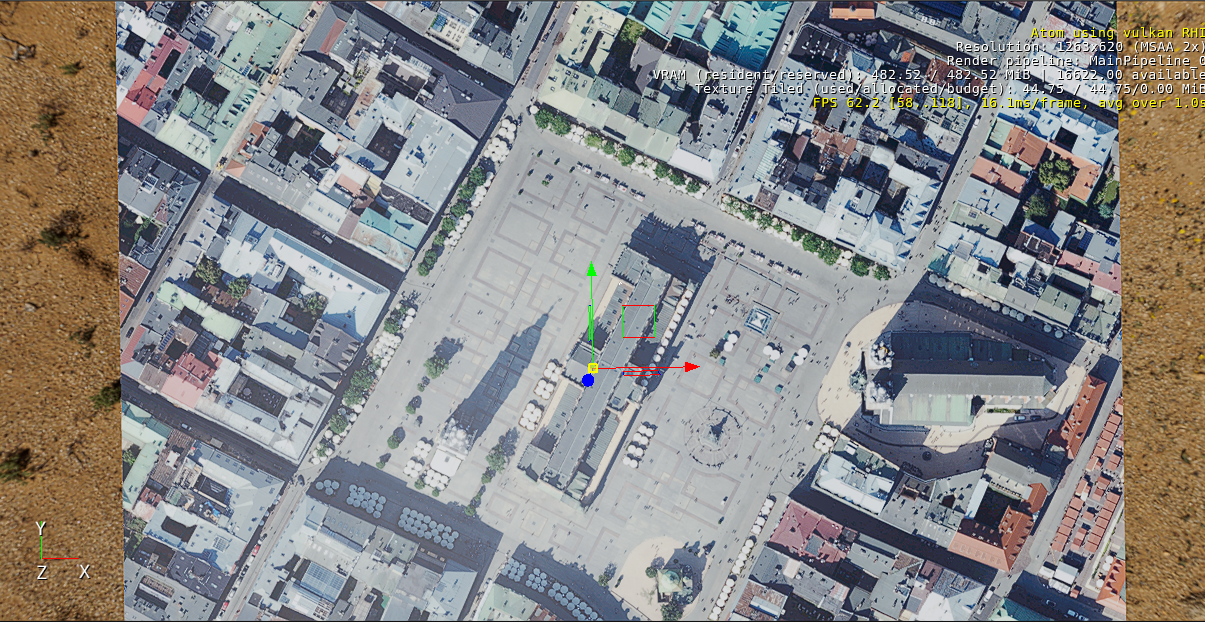
Note:The ENU entity does not need any additional components.
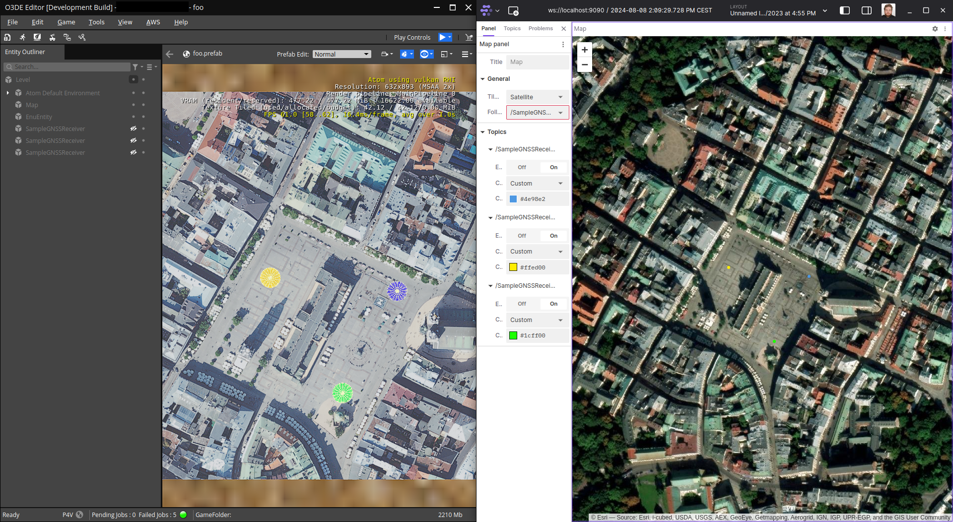
You can test if everything works as expected by placing a few simulated GNSS sensors from ROS 2 Gem and moving them on the scene. In the example shown in the image below, there are three similar GNSS sensors in places marked with colored spheres in the O3DE editor on the left. On the right, you can see NavSat messages produced by those GNSS sensors visualized in Foxglove studio .