IN THIS ARTICLE
Script Canvas Nodes
A node in Script Canvas consists of a title bar, inputs, and outputs.
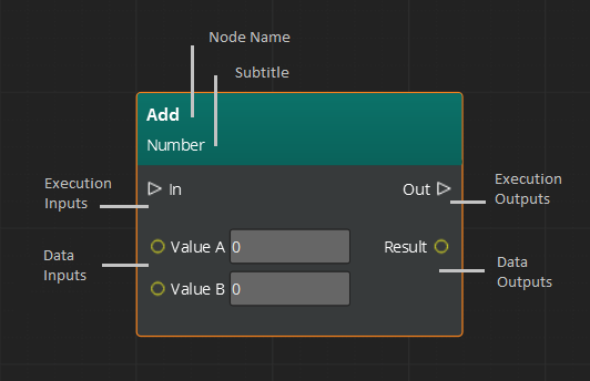
Title Bar - The title bar of a node is in a colored band at the top of the node. A title bar can include a subtitle, but not all nodes have subtitles.
Inputs - Located on the left side of the node. There are two types of input nodes: execution and data. Execution inputs drive the flow of execution of a script into a given node. Data inputs provide the node with the data it requires to do processing or decision making.
Outputs - Located on the right side of the node. Execution and data output nodes drive the flow of execution and data into any connected nodes.
Inputs, outputs, and connection types
Open 3D Engine (O3DE) has two main pin and connection types. Some inputs and outputs determine the flow of logic and order of execution. Other inputs and outputs pass data from one node to the next.
Logic inputs, outputs, and connections
The execution of a script is driven by triangular inputs and outputs on every node. These connections determine the order of execution. A Script Canvas script runs when the entity that is attached to the script is activated. Nodes are connected from the inputs on their left side. After they finish running, they activate nodes that are connected to their outputs on the right side.
An output logic pin with multiple connections runs a logic branch in sequence. The execution sequence is determined by the order that the connections were made, from earliest to most recent. If a specific execution order is required, you can specify the sequence order by using a single logic flow or a Sequencer node.
An incoming logic pin with multiple connections runs each time that the logic flow triggers the node. For example, if a node is triggered by three different nodes in a script, the node runs three times.
Data inputs, outputs, and connections
Data connections enable scripts to read and write data between nodes. Data is read from the right side of one node and then set on the left side of another node.
Making connections
You can make connections only between pins of the same type. For example, you make logic connections only between logic pins, and data connections only between data pins of the same type. You can’t create connections between incompatible pins, such as logic and data.
To make a connection
In the Script Canvas Editor canvas, drag from the input pin of one node to an output pin of another node. This creates a connection line between the two pins.
To move a connection from one pin to another, drag the end of a line from one pin and drop it onto another pin.
To delete a connection, right-click and choose Delete. You can also press and hold Alt, and choose the connection to delete it.
Variable nodes
Variable nodes enable Script Canvas to read from or write to specific variables.
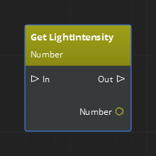
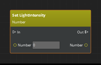
Another way to read or write a variable—without the need for a separate variable node—is to use variable references on a node data pin.
For more information about using variables in Script Canvas, refer to Script Canvas Variables and the Variable Manager.
Event nodes
In O3DE’s Event Bus (EBus) system, events can be sent or received. Script Canvas surfaces this system through the use of sender nodes and receiver nodes.
Sender nodes
Event senders send events directly to a specific entity or broadcast events to all entities that are listening for and interested in handling the event. Most events are addressable, which means they can be sent to a specific entity. Because events are usually sent to entities, the most common address type is Entity Id, although other address types can be used.
The following example uses Light events to create a sender node.
To create a sender node
In the Node Palette search box, type Light. The results show nodes related to light.
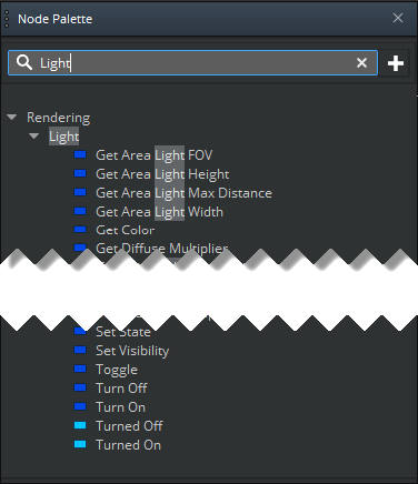
In the Node Palette, sender events are the dark blue entries. All Light-related sender events provide a way to communicate with, configure, or alter the behavior of a given Light component. You can send any of the Light-related sender events to an entity that has a Light component. If the entity that owns the Script Canvas graph also has a Light component, it can send the event to itself.
Drag Turn On or Turn Off onto the canvas to create a sender node.
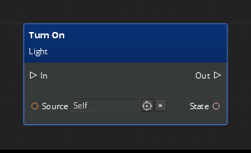
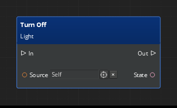
The Source pin of the sender node refers to the entity that sends the event. The default is Self, which means that it sends Light events for the same entity that the Script Canvas component is on. However, you can change the source to any entity in the game world.
The State pin is a Boolean value that controls the state of the light.
Receiver nodes
An event receiver implements a particular behavior when it receives a particular event.
The following example creates a receiver node for a Light event.
To create a receiver node
In the Node Palette search box, type Turn.
In the list of results, event receivers like Turned Off and Turned On have a light blue icon.
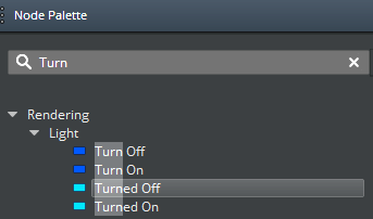
Drag Turned On onto the canvas to create a receiver node.
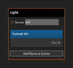
The Source pin of the receiver node refers to the entity from which the event is received. The default is Self, which means the node receives Light events for the same entity that the Script Canvas component is on. You can change the target to any entity in the game world.
You can also specify the target using a variable reference. Whenever the variable changes, the EBus handler will update the Source to match the variable reference.
Click Add/Remove Events.
Because receiver nodes are usually containers for multiple events, you can choose Add/Remove Events to view and add any of the available event receivers for a given component. In this case, the Light component exposes two events: Turned Off and Turned On.
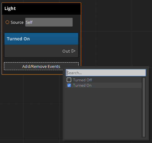
Select the Turned Off check box to add the Turned Off event to the receiver node.
A second blue band in the node appears. The node is now listening for both the Turned On and Turned Off events.
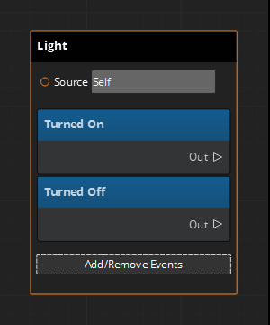
Click Add/Remove Events again, and clear the Turned Off check box. The Turned Off event is removed from the receiver node.
Displaying and using connection controls
All receiver nodes have connection-related pins, or controls, that are hidden by default. You can use these controls to manage when an event is connected or disconnected. Connected means that the event is ready to receive events, and disconnected means that the event is not receiving events. The connection controls can also notify you when a node successfully connects, disconnects, or experiences an error.
The following example uses the Light component Turned On event node.
To enable and use Display Connection Controls
Ensure that Node Inspector is visible. In Script Canvas Editor, choose View, Node Inspector, or press Ctrl+Shift+I.
Choose the Light Turned On node to select it.
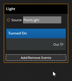
In Node Inspector, select Display Connection Controls.
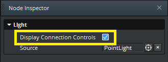
The Light component Turned On receiver node expands to provide connection-related pins.
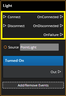
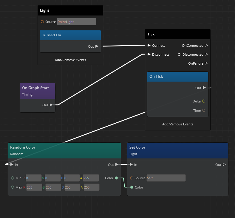
Connect and Disconnect - Use the Disconnect pin to prevent the receiver node from connecting. When the event should be connected and available to receive events, use the Connect pin.
The Connect and Disconnect pins are especially useful when working with the On Tick event. For example, if you have a complex operation that you do not want processed for every tick of the game, you can disconnect the On Tick event until it is required.
Note:When you enable a receiver node’s Display Connection Controls property, the node no longer connects automatically. In this case, Script Canvas assumes that you want to specify when the connection occurs.OnConnected - Triggered when the event connects successfully. This pin is useful if you want to continue execution along the connection path when the connection occurs.
OnDisconnected - Triggered when the event disconnects successfully. This pin is useful if you want to continue execution along the disconnection path when the connection occurs.
OnFailure - An event fails to connect if it requires a source and no source is provided, or an invalid source is provided. The OnFailure pin displays diagnostic information that you can use to verify whether address data was correctly specified to the Source pin of the receiver node.
Example
In the following example, Display Connection Controls is enabled for the On Tick event receiver node. The Tick event is disconnected at the start of the graph’s lifetime. When the light is turned on, the example changes the light’s color randomly for every tick.
