IN THIS ARTICLE
Setting up a Ragdoll
Important:There is currently no automatic way to prevent the physics geometry PhysX Character Controller component from colliding with the PhysX Ragdoll component, which can lead to unexpected behavior for the ragdoll. Collisions can be avoided by using collision filtering or by disabling the physics on the PhysX Character Controller component when the ragdoll is activated.
To set up a ragdoll, do the following:
In addition, your actor must have a motion extraction node. Your ragdoll must have a root node that is a direct child of the motion extraction node. For example, the Rin character uses root for its motion extraction node. For the ragdoll root node, the Rin character uses C_pelvis_JNT, which is a child node of root.
While working on ragdoll setup, it can be useful to show or hide certain elements in the Atom Render Window. You can use the render options dropdown, represented by the 
Step 1: Define Joints for the Ragdoll
Do the following to select the joints for your ragdoll. Usually you will want to include significantly fewer joints in the ragdoll than are present in the animation skeleton, as simulating small joints such as finger bones typically creates little benefit and incurs performance costs.
To select joints for the ragdoll
In O3DE Editor, choose Tools, Animation Editor.
In the Animation Editor, on the right side of the menu bar, choose Physics from the drop-down list. This changes the layout.
Choose File, Open Actor and select your actor.
In the Skeleton Outliner, multi-select the joints that you want to include in your ragdoll. You can also select individual joints by left clicking on the Line Skeleton view in the Atom Render Window.
Right-click one of the selected joints and then choose Ragdoll, Add to ragdoll.
Note:You can add joints to the ragdoll at any time.Note:If a joint is added to the ragdoll, all of its ancestors are automatically added as well. This can be useful as a quick way to add a complete hierarchy just by adding a few end effectors, e.g. joints in the hands, feet and head. Similarly if a joint is removed from the ragdoll, all of its descendants are also removed.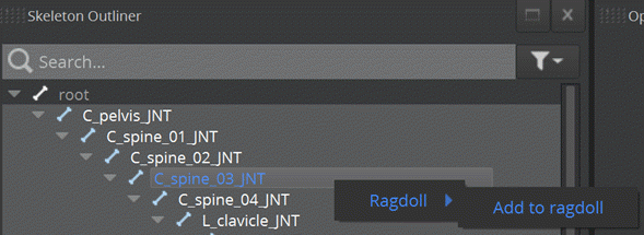
Click the filter
icon next to the search text box, and select Ragdoll joints and colliders. This shows only the joints in the ragdoll and not the full animation skeleton.
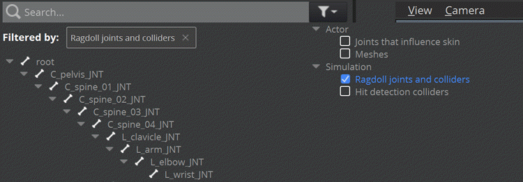
The Skeleton Outliner displays icons to indicate that:
A joint is part of the ragdoll
A joint holds ragdoll colliders
A joint holds hit detection colliders
A joint holds cloth colliders

In the Atom Render Window, use the render options dropdown, represented by the
icon, to show or hide the ragdoll colliders (rendered in orange), ragdoll joint limits, hit detection colliders (rendered in blue), and cloth colliders (rendered in purple).
Note:If your ragdoll colliders, hit detection colliders, or cloth colliders are the same size, you may need to hide the colliders that you are not working on.On the Inspector tab, you can view and modify the ragdoll properties for the selected joint. For example, the rigid body mass, sleeping threshold, and colliders.
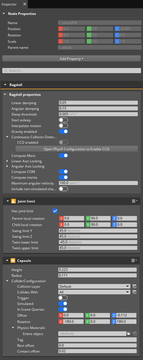
Step 2: Set up Ragdoll Colliders
Adding and removing ragdoll colliders
Each joint in the ragdoll can have 0, 1, or multiple ragdoll colliders, which affect how the ragdoll collides with other physical objects. Box, sphere, and capsule geometries are supported. By default, when a joint is added to the ragdoll, it is automatically created with a capsule collider which roughly approximates the shape of the parts of the actor mesh most heavily influenced by that joint. If a different geometry would work better, you can delete the default collider and add another as described below.
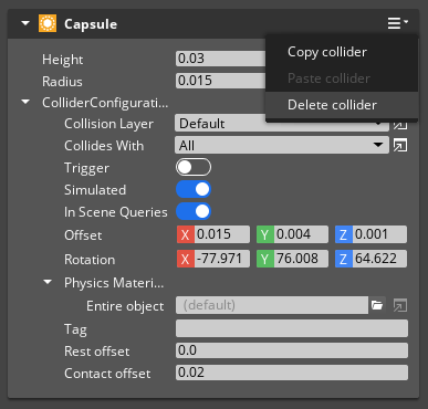
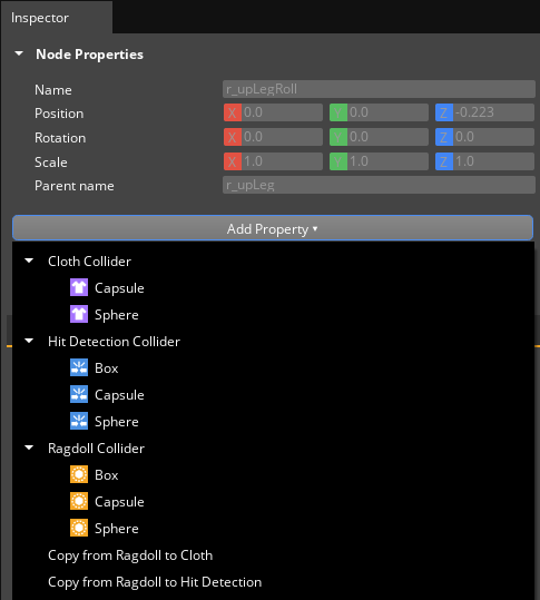
To add a collider, in the Animation Editor, on the Inspector tab, click Add Property and then under Ragdoll Collider section choose Box, Capsule or Sphere. You can also copy colliders from the Hit Detection or Cloth configurations, if you have already created colliders for them.
Configuring properties for colliders
Joints in the ragdoll can be selected using the Skeleton Outliner or by clicking on the Line Skeleton or Ragdoll Collider views in the Atom Render Window. If a single joint is selected, you can adjust the Offset (position) and Rotation for colliders, and the Height and Radius for Capsule colliders using manipulators which are accessible from a Viewport UI Cluster in the top left of the Atom Render Window. Different manipulator modes can be selected by clicking on the following icons in the Viewport UI Cluster.
| Mode | Icon | Description |
|---|---|---|
| Offset |  | Activates manipulators allowing the position of the collider relative to its joint to be modified. This mode will be available if the joint has at least one ragdoll collider. |
| Rotation |  | Activates manipulators allowing the rotation of the collider relative to its joint to be modified. This mode will be available if the joint has at least one ragdoll collider. |
| Dimensions |  | Activates manipulators allowing the Height and Radius of a Capsule collider to be modified. This mode will be available if the joint has at least one ragdoll collider and its first collider has Capsule geometry. |
Note:Currently, if a joint has more than one ragdoll collider, manipulators only support editing the first collider.
If you have more than one ragdoll collider, or if you prefer to edit values directly, you can also configure collider properties in the property editor.
On the Inspector tab, do the following in the ragdoll collider properties:
Set the Offset and Rotation to move the collider to the correct location. The Offset and Rotation are relative to the joint transform.
Adjust the collider dimensions (for example, set the Height and Radius for a Capsule) to resize the collider.
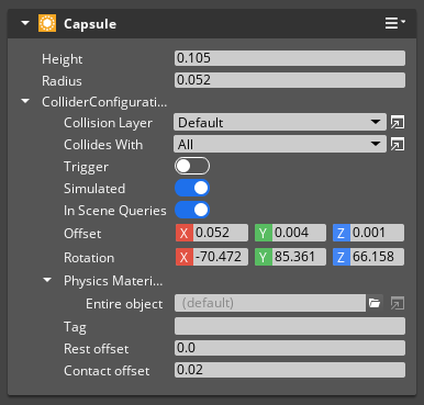
You can also set up other properties in the property editor, such as the physics material and collision filtering.
Saving changes
Choose File, Save Selected Actors. This saves the ragdoll data to the .assetinfo file for the character. The Asset Processor then bakes the ragdoll data into the .actor file.
Avoiding self-collision
The ragdoll automatically suppresses collisions between joints that are adjacent in the skeleton. This means that adjacent colliders can overlap, but a pair of colliders that are not adjacent should not intersect. If the pair of colliders intersects, they’ll collide when the ragdoll is simulated. This leads to unstable behavior, because the colliding bodies are trying to separate, while the joints are trying to keep the ragdoll together. If two joints which are not adjacent in the hierarchy have overlapping colliders, the colliders will be rendered in red, as shown below.
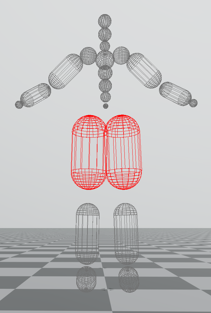
To resolve the overlap, you can resize the colliders or use collision filtering so that they do not collide with each other.
Step 3: Create Joint Limits
Joint limits allow the range of motion of joints to be restricted to avoid unrealistic poses. For example, a human character’s knee joint will appear unnatural if it extends past the position where the leg becomes straight. In PhysX, joint limits are separated into two parts, Swing Limits and Twist Limits. To understand these two limits, consider an elbow joint as a concrete example. The elbow creates a joint between two body parts, the upper arm (referred to below as the parent) and the forearm (child).
The Twist Limit describes rotations around an axis rigidly attached to the child. That axis can be orientated arbitarily relative to the child during the setup of the joint limit, but it is usually easiest to visualize if it points directly along the child (from the elbow to the wrist in the example). If you imagine holding your arm out straight in front of you, you can rotate around the forearm so that your palm is face up or face down, but it is uncomfortable to rotate much further in either direction, i.e. there is a limit to how much you can twist around that axis. If you were holding a pen between your fingers at right angles to your palm, then the pen would describe a fan shape as you rotate your forearm.
The Swing Limit describes how the axis attached to the child can move relative to the parent. Continuing with the elbow example, if you consider holding your upper arm still, you can bend your elbow so that your hand touches your shoulder, or extend it so that the arm is straight. There is also a range of motion to the left or right (think about arm wrestling). Overall, you can imagine a cone rigidly attached to the upper arm which describes the full range of possible orientations for the forearm. Note that because the range of motion of the forearm is not symmetrical (you can bend your elbow more in some directions than in others), the cone needs to be rotated relative to the direction of the upper arm.
Putting all this together, there are several parameters which can be configured for each joint limit:
- The axis attached to the child body of the joint, which is rendered as a long arrow. It is usually easiest to align this to point along the child body, and joint limits will automatically be configured that way when they are first created.
- The orientation of the Swing Limit, which is rendered as a cone, relative to the parent body.
- The angular extents of the Swing Limit cone.
- The minimum and maximum values for the Twist Limit, which is rendered as a fan shape.
If a single joint is selected, these parameters can be modified using manipulators accessible through a Viewport UI Cluster at the top left of the Atom Render Window (below the collider cluster if it is available). Different manipulator modes can be selected by clicking on the following icons in the Viewport UI Cluster.
| Mode | Icon | Description |
|---|---|---|
| Parent local rotation |  | Activates manipulators allowing the rotation of the joint parent frame to be modified. This allows the cone for the swing limit cone and the arc for the twist limit to be orientated relative to the frame of the joint’s parent. |
| Child local rotation |  | Activates manipulators allowing the rotation of the joint child frame to be modified. This allows the axis which moves around inside the joint limit to be orientated relative to the joint’s frame. |
| Swing Limit |  | Activates manipulators allowing the size of the swing limits in the Y and Z directions to be modified. |
| Twist Limit |  | Activates manipulators allowing the mininum and maximum twist limits to be modified. |
| Joint Limit Automatic Fit |  | Computes an optimal joint limit based on sampling poses from a loaded Motion Set. In order to use this feature, you will need to load a Motion Set in the Motion Sets panel. |
The joint limit configuration can also be adjusted using the property editor.
If the current pose for the Actor causes the Swing Limit or Twist Limit to be violated, that limit will be rendered in red.
